Frequency inverter cable impact on Motor Life
Reflected waves caused by a cable-to-motor impedance mismatch are prevalent in all frequency inverter applications. The magnitude of the problem depends on the length of the cable, the rise-time of the PWM (pulse width modulated) carrier wave, the voltage of the frequency inverter, and the magnitude of the impedance difference between the motor and cable.
Under the right conditions, a pulse from the frequency inverter can add to a pulse reflected back from the motor to result in a doubling of voltage level, which could damage the cable or the components inside the inverter. A solution is use of XLPE cable insulation, a material with high impulse voltage breakdown levels, that makes it more immune to failure from reflected wave and voltage spikes in a frequency inverter application than, say, PVC, a material which is not recommended in these applications.
Because cable length is mostly determined by the layout of the application, while rise times vary with the frequency inverter output semiconductor and the voltage of the frequency inverter is determined by the application, the impedance of the cable relative to the motor will be the primary mechanism outlined in this paper.
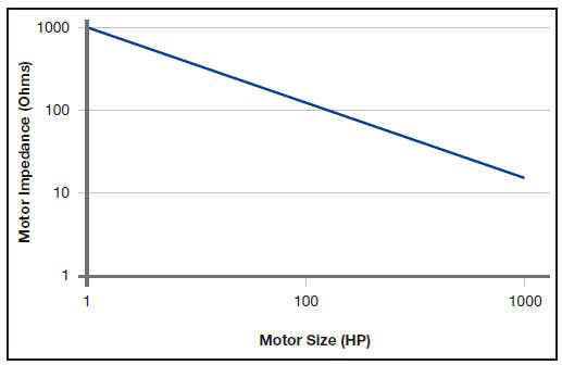
First, let's look at estimated motor impedance relative to motor size in HP over a range of horsepower ratings, as indicated in Following Figure. Note that the cable impedance for 1HP motor/inverter combinations would need to be roughly 1,000 ohms to match the corresponding motor's impedance. Unfortunately, a cable with such high characteristic impedance would require conductor spacing in excess of several feet. Obviously, this would be both impractical and very expensive.

In addition to other benefits, such as reduced capacitance, a more closely matched impedance can improve motor life. Table 1 lists the observed line-to-line peak motor terminal voltages, as well as the impedance of the cables under test. The voltage measurements were taken using 120 ft. cable lengths.
Table 1
Table 1 shows typical impedance values for #12 AWG circuit conductors and is based on actual data. Cable impedance is influenced both by its geometry and materials used in its manufacture. The characteristic impedance of a cable is calculated using the following formula, where Zc = characteristic impedance, L = cable inductance, and C = cable capacitance.
In Table 1, note the inversely proportional relationship between the cable's impedance and the peak motor terminal voltage: cables with higher impedance tended to result in lower peak motor terminal voltages. A cable's design for impedance also impacts its useful life. Lower voltages across the motor terminals translate into the cable being exposed to lower voltages, increasing its life expectancy.
In addition, this reduces the likelihood of either the cable or the motor reaching its corona inception voltage (CIV). That's the point at which the air gap between two conductors in the cable, or two windings on the motor, breaks down via arcing or a spark under the high potential difference. If the CIV is reached, insulation failure can occur in the windings of the motor.
Corona discharge occurring between conductors of the cable can produce very high temperatures. If the insulation system of the cable is a thermoplastic material such as PVC, the phenomenon can cause premature cable burn-out or a short circuit due to a gradual, localized melting of the insulation. For this reason alone, thermoplastic insulations should not be used for frequency inverter applications.
On the other hand, thermoset insulation systems such as those based on XLPE are ideal materials for these applications because of the high temperature stability they exhibit. In their case, the heat generated from corona forms a thermally-isolating charred layer on the surface of the insulation, preventing further degradation. All cables used for frequency inverters should use a thermoset insulation system as a precautionary measure.
Under the right conditions, a pulse from the frequency inverter can add to a pulse reflected back from the motor to result in a doubling of voltage level, which could damage the cable or the components inside the inverter. A solution is use of XLPE cable insulation, a material with high impulse voltage breakdown levels, that makes it more immune to failure from reflected wave and voltage spikes in a frequency inverter application than, say, PVC, a material which is not recommended in these applications.
Because cable length is mostly determined by the layout of the application, while rise times vary with the frequency inverter output semiconductor and the voltage of the frequency inverter is determined by the application, the impedance of the cable relative to the motor will be the primary mechanism outlined in this paper.
First, let's look at estimated motor impedance relative to motor size in HP over a range of horsepower ratings, as indicated in Following Figure. Note that the cable impedance for 1HP motor/inverter combinations would need to be roughly 1,000 ohms to match the corresponding motor's impedance. Unfortunately, a cable with such high characteristic impedance would require conductor spacing in excess of several feet. Obviously, this would be both impractical and very expensive.

In addition to other benefits, such as reduced capacitance, a more closely matched impedance can improve motor life. Table 1 lists the observed line-to-line peak motor terminal voltages, as well as the impedance of the cables under test. The voltage measurements were taken using 120 ft. cable lengths.
Table 1
| Cable Type | Impedance (ohms) | Voltage at Motor Terminals |
| Continuous Aluminum Armored Cable | 87 | 1080 V |
| Foil/Braid frequency inverter Cable 2950X Series | 78 | 1110 V |
| Cu-Tape Shielded frequency inverter Cable | 58 | 1150 V |
| Unshielded PVC-Nyl/PVC | 58 | 1150 V |
| Shielded PVC-Nyl/PVC | 38 | 1260 V |
Table 1 shows typical impedance values for #12 AWG circuit conductors and is based on actual data. Cable impedance is influenced both by its geometry and materials used in its manufacture. The characteristic impedance of a cable is calculated using the following formula, where Zc = characteristic impedance, L = cable inductance, and C = cable capacitance.
In Table 1, note the inversely proportional relationship between the cable's impedance and the peak motor terminal voltage: cables with higher impedance tended to result in lower peak motor terminal voltages. A cable's design for impedance also impacts its useful life. Lower voltages across the motor terminals translate into the cable being exposed to lower voltages, increasing its life expectancy.
In addition, this reduces the likelihood of either the cable or the motor reaching its corona inception voltage (CIV). That's the point at which the air gap between two conductors in the cable, or two windings on the motor, breaks down via arcing or a spark under the high potential difference. If the CIV is reached, insulation failure can occur in the windings of the motor.
Corona discharge occurring between conductors of the cable can produce very high temperatures. If the insulation system of the cable is a thermoplastic material such as PVC, the phenomenon can cause premature cable burn-out or a short circuit due to a gradual, localized melting of the insulation. For this reason alone, thermoplastic insulations should not be used for frequency inverter applications.
On the other hand, thermoset insulation systems such as those based on XLPE are ideal materials for these applications because of the high temperature stability they exhibit. In their case, the heat generated from corona forms a thermally-isolating charred layer on the surface of the insulation, preventing further degradation. All cables used for frequency inverters should use a thermoset insulation system as a precautionary measure.

 High quality frequency inverters for electric motor speed controls in energy-saving solutions.

