Frequency Converter Troubleshooting
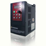
Frequency converters can be powerful tools in maintaining processes by using diagnostics to solve frequency inverter performance issues and troubleshoot related processes. An understanding of how the frequency converter interacts with the process can help you improve overall production and product quality (Fig. 1).

Frequency converters are not infallible; sometimes they need to be repaired or replaced. The frequency converter is often the first indicator of a process change or application problem.
Many frequency converters communicate using an LCD or LED display, or through an open interlock or fault indication. In most applications, the frequency converter interacts with operator controls, process control signals, and PLCs. A problem with the interaction between the frequency converter and these external controls may appear to be a frequency inverter issue, when actually the problem is with the process. Discussing process and frequency inverter symptoms with the machine operators often can help determine the problem area.
If the external controls are working correctly, use the frequency converter to identify problems systematically. If the display status indicator does not operate, verify incoming ac power. If the status indicator still does not display after verifying or restoring ac power, then verify control power, and restore it if necessary.
If the frequency converter has been operating successfully, but suddenly fails to start, or if the frequency inverter starts but does not run properly, check to see if the diagnostics status display indicates a fault. The instruction manual for the frequency converter should have a description of faults and troubleshooting steps. Use diagnostics or a keypad control to monitor variables such as incoming voltage, dc bus, carrier frequency, output frequency, voltage, current, and I/O and control status. These parameters are displayed on most common frequency converters. I/O status uses bits to monitor required start conditions to ensure they are enabled and to determine what may be inhibiting start. Control status indicates the source of the speed reference and can be used to verify incoming speed or direction signals.
High bus fault
High bus is a common fault caused by external factors. An instantaneous voltage spike in the ac line or an "overhauling load" created by the inertia of the machine can cause a high bus fault. The load continues to rotate faster than the motor's commanded speed. When this situation occurs, the frequency converter protects itself by tripping on a high bus fault and shutting off the insulated gate bipolar transistors (IGBTs).
If a high bus fault is indicated, ensure that the ac power supply is consistent and that the deceleration time is adjusted to match the capability of the load. If the process requires rapid deceleration, dynamic braking or a regenerative power control circuit may be added.
Overcurrent fault
Another common fault is overcurrent. When troubleshooting overcurrent faults, first check all power connections to ensure that they are properly attached. Loose connections or broken conductors frequently are culprits when overcurrent and control problems occur. Loose power connections cause overvoltage and overcurrent conditions, blown fuses, and frequency converter damage. Loose control wiring causes erratic frequency inverter performance, resulting in unpredictable speed fluctuations or the inability to control the frequency converter.
Use an autotuning feature if it is offered on the frequency converter. The autotuning function on many frequency inverters enables the frequency inverter to identify the attached motor, allowing rotor information to be used in the processor algorithms for more accurate current control. The frequency converter also can compensate for flux current, allowing better control of the torque-producing current. Both over and under fluxing the motor can be troublesome.
The second step is to check the mechanical load for worn or broken parts, or excessive friction. Repair or replace components as needed.
Finally, check incoming voltage and acceleration rate. If incoming voltage is too low, or the acceleration rate is set too fast, an overcurrent fault is possible. Decrease the acceleration rate or stabilize incoming voltage to correct this fault.
High starting-load current
High current/load readings may indicate mechanical binding or unexplained changes in process speed or load. The power requirements for many pumps and fans increase proportional to the cube of the rotational speed (S3). Running loads just a few revolutions per minute faster can overload a frequency converter.
Components should be checked before startup to avoid an overload situation. Conveyors left loaded during off hours should be unloaded before startup. Clogged pumps should be avoided by cleaning out solids that have settled while the pump was not in use. Avoid ice or moisture that possibly could form on the load. Wet material is heavier than dry and can place more loading on the conveyor, causing motor and frequency converter overload.
One way to reduce a high starting load is to use a frequency converter with an extended acceleration rate. This feature starts a load slowly and smoothly rather than jerking it to a start. This type of start is easier on mechanical components and has lower line requirements because the frequency converter draws only 100% MDASSML 150% of load.
Erratic operation
If the frequency converter is functioning erratically, but a fault is not indicated, external factors may be the cause, or the frequency inverter itself may have failed. Understanding the causes of frequency converter faults helps you determine the root cause of the problem. Frequently overlooked root causes are usually instabilities in the process that force the frequency converter to function in harsh conditions.
Visually inspect the frequency converter for burned or overheated components by looking for signs of discoloration or cracking. Burned or cracked components prevent proper frequency converter operation. Replace defective components and test the frequency converter before returning it to operation.
Power quality is another electrical issue that can affect a frequency converter. A change in utility equipment or unexpected power surges, due to electrical storms or system overloads, can affect frequency converter performance.
Contamination failure
Contamination is a preventable cause of frequency converter failure. Check the frequency converter for contamination of dust, moisture, or other airborne particles that may be electrically conductive. Tracking or arcing marks across components or circuit board traces indicate evidence of contamination failures. If contamination is excessive, the frequency converter must be isolated from the contamination source by changing the environment or providing an appropriate NEMA-rated enclosure. If there is significant airborne contamination from dust, moisture, or corrosive vapors, the frequency converter must be in at least a NEMA-12 enclosure.
The internal cooling fans and component heatsinks of the frequency converter also should be checked for contamination. Blocked fans force the frequency converter to operate outside of its temperature specification, which can cause premature failure as a result of inadequate cooling. Check the fan for grease and other contaminants that can cause bearings and other parts of the fan to fail. Both the interior and exterior of the frequency converter, including fans, blowers, filters, and heatsink fins, should be cleaned monthly to reduce the risk of failure from contaminants.
Temperature failure
The environment within which the frequency inverter must operate must be within specified temperature limits. Measure the temperature inside and outside the enclosure to ensure that it is within the ambient specifications determined by the manufacturer. Failure to meet the required temperature specifications can lead to premature frequency converter failure because numerous power components rely on adequate cooling for proper operation.
If the ambient temperature is too high, additional cooling should be added to the enclosure or the frequency converter should be relocated to an area where the ambient temperature is within the specification. Low ambient temperatures may cause problems as well. Condensation may form and cause component or frequency converter failure.
Other failures
Many faults are caused by misapplication of the frequency converter. Process changes, such as variations in load or speed; power issues, such as capacity switching by the utility; or changes in environmental operating conditions are not immediately obvious, but could be a major contributor to frequency converter failure. Evaluate the consistency and condition of the process when trying to determine the cause of failure.
If the frequency converter remains inoperative after performing the aforementioned checks, contact the manufacturer. Most frequency converter suppliers have highly trained technical support personnel that can provide the assistance needed to diagnose the problem. The technical support staff can help you select replacement parts or a new frequency inverter if replacement is necessary.
As intelligent devices embedded in the manufacturing process, frequency converters can provide insight into application and equipment performance. By providing the maintenance worker with the information necessary to understand and interpret the problem, frequency converter issues, and sometimes process or operational problems, can be quickly identified so that plant operation can be resumed and productivity improved.
Talking with machine operators
Talking with machine operators can often identify the problem area. Useful questions to ask are:
When a process requires a frequency inverter and motor to decelerate rapidly, the motor can actually operate as a generator. The energy stored within the motor in the form of mechanical rotation must go somewhere. A dynamic braking circuit is used to accommodate this energy.
A dynamic braking circuit is a switch that monitors the dc bus and turns on when the bus level exceeds a certain setpoint. Energy is delivered to the resistors, and is expended in heat until the bus level drops below that setpoint.
A regenerative power supply operates as an inverter-in-reverse, which allows synchronization of the IGBT firing circuits with the incoming ac line. Using a regenerative power supply allows the circuit, which is separate from and external to the frequency inverter, to send the excess energy from the motor through the dc bus back to the power source.
Frequency converters are not infallible; sometimes they need to be repaired or replaced. The frequency converter is often the first indicator of a process change or application problem.
Many frequency converters communicate using an LCD or LED display, or through an open interlock or fault indication. In most applications, the frequency converter interacts with operator controls, process control signals, and PLCs. A problem with the interaction between the frequency converter and these external controls may appear to be a frequency inverter issue, when actually the problem is with the process. Discussing process and frequency inverter symptoms with the machine operators often can help determine the problem area.
If the external controls are working correctly, use the frequency converter to identify problems systematically. If the display status indicator does not operate, verify incoming ac power. If the status indicator still does not display after verifying or restoring ac power, then verify control power, and restore it if necessary.
If the frequency converter has been operating successfully, but suddenly fails to start, or if the frequency inverter starts but does not run properly, check to see if the diagnostics status display indicates a fault. The instruction manual for the frequency converter should have a description of faults and troubleshooting steps. Use diagnostics or a keypad control to monitor variables such as incoming voltage, dc bus, carrier frequency, output frequency, voltage, current, and I/O and control status. These parameters are displayed on most common frequency converters. I/O status uses bits to monitor required start conditions to ensure they are enabled and to determine what may be inhibiting start. Control status indicates the source of the speed reference and can be used to verify incoming speed or direction signals.
High bus fault
High bus is a common fault caused by external factors. An instantaneous voltage spike in the ac line or an "overhauling load" created by the inertia of the machine can cause a high bus fault. The load continues to rotate faster than the motor's commanded speed. When this situation occurs, the frequency converter protects itself by tripping on a high bus fault and shutting off the insulated gate bipolar transistors (IGBTs).
If a high bus fault is indicated, ensure that the ac power supply is consistent and that the deceleration time is adjusted to match the capability of the load. If the process requires rapid deceleration, dynamic braking or a regenerative power control circuit may be added.
Overcurrent fault
Another common fault is overcurrent. When troubleshooting overcurrent faults, first check all power connections to ensure that they are properly attached. Loose connections or broken conductors frequently are culprits when overcurrent and control problems occur. Loose power connections cause overvoltage and overcurrent conditions, blown fuses, and frequency converter damage. Loose control wiring causes erratic frequency inverter performance, resulting in unpredictable speed fluctuations or the inability to control the frequency converter.
Use an autotuning feature if it is offered on the frequency converter. The autotuning function on many frequency inverters enables the frequency inverter to identify the attached motor, allowing rotor information to be used in the processor algorithms for more accurate current control. The frequency converter also can compensate for flux current, allowing better control of the torque-producing current. Both over and under fluxing the motor can be troublesome.
The second step is to check the mechanical load for worn or broken parts, or excessive friction. Repair or replace components as needed.
Finally, check incoming voltage and acceleration rate. If incoming voltage is too low, or the acceleration rate is set too fast, an overcurrent fault is possible. Decrease the acceleration rate or stabilize incoming voltage to correct this fault.
High starting-load current
High current/load readings may indicate mechanical binding or unexplained changes in process speed or load. The power requirements for many pumps and fans increase proportional to the cube of the rotational speed (S3). Running loads just a few revolutions per minute faster can overload a frequency converter.
Components should be checked before startup to avoid an overload situation. Conveyors left loaded during off hours should be unloaded before startup. Clogged pumps should be avoided by cleaning out solids that have settled while the pump was not in use. Avoid ice or moisture that possibly could form on the load. Wet material is heavier than dry and can place more loading on the conveyor, causing motor and frequency converter overload.
One way to reduce a high starting load is to use a frequency converter with an extended acceleration rate. This feature starts a load slowly and smoothly rather than jerking it to a start. This type of start is easier on mechanical components and has lower line requirements because the frequency converter draws only 100% MDASSML 150% of load.
Erratic operation
If the frequency converter is functioning erratically, but a fault is not indicated, external factors may be the cause, or the frequency inverter itself may have failed. Understanding the causes of frequency converter faults helps you determine the root cause of the problem. Frequently overlooked root causes are usually instabilities in the process that force the frequency converter to function in harsh conditions.
Visually inspect the frequency converter for burned or overheated components by looking for signs of discoloration or cracking. Burned or cracked components prevent proper frequency converter operation. Replace defective components and test the frequency converter before returning it to operation.
Power quality is another electrical issue that can affect a frequency converter. A change in utility equipment or unexpected power surges, due to electrical storms or system overloads, can affect frequency converter performance.
Contamination failure
Contamination is a preventable cause of frequency converter failure. Check the frequency converter for contamination of dust, moisture, or other airborne particles that may be electrically conductive. Tracking or arcing marks across components or circuit board traces indicate evidence of contamination failures. If contamination is excessive, the frequency converter must be isolated from the contamination source by changing the environment or providing an appropriate NEMA-rated enclosure. If there is significant airborne contamination from dust, moisture, or corrosive vapors, the frequency converter must be in at least a NEMA-12 enclosure.
The internal cooling fans and component heatsinks of the frequency converter also should be checked for contamination. Blocked fans force the frequency converter to operate outside of its temperature specification, which can cause premature failure as a result of inadequate cooling. Check the fan for grease and other contaminants that can cause bearings and other parts of the fan to fail. Both the interior and exterior of the frequency converter, including fans, blowers, filters, and heatsink fins, should be cleaned monthly to reduce the risk of failure from contaminants.
Temperature failure
The environment within which the frequency inverter must operate must be within specified temperature limits. Measure the temperature inside and outside the enclosure to ensure that it is within the ambient specifications determined by the manufacturer. Failure to meet the required temperature specifications can lead to premature frequency converter failure because numerous power components rely on adequate cooling for proper operation.
If the ambient temperature is too high, additional cooling should be added to the enclosure or the frequency converter should be relocated to an area where the ambient temperature is within the specification. Low ambient temperatures may cause problems as well. Condensation may form and cause component or frequency converter failure.
Other failures
Many faults are caused by misapplication of the frequency converter. Process changes, such as variations in load or speed; power issues, such as capacity switching by the utility; or changes in environmental operating conditions are not immediately obvious, but could be a major contributor to frequency converter failure. Evaluate the consistency and condition of the process when trying to determine the cause of failure.
If the frequency converter remains inoperative after performing the aforementioned checks, contact the manufacturer. Most frequency converter suppliers have highly trained technical support personnel that can provide the assistance needed to diagnose the problem. The technical support staff can help you select replacement parts or a new frequency inverter if replacement is necessary.
As intelligent devices embedded in the manufacturing process, frequency converters can provide insight into application and equipment performance. By providing the maintenance worker with the information necessary to understand and interpret the problem, frequency converter issues, and sometimes process or operational problems, can be quickly identified so that plant operation can be resumed and productivity improved.
Talking with machine operators
Talking with machine operators can often identify the problem area. Useful questions to ask are:
- What was happening with the machine at the time of failure?
- Did the machine jam?
- Did other devices trip at the same time as the frequency inverter?
- Was there an electrical shutdown caused by lighting storm or brown-out?
- Was there construction such as welding going on around the frequency inverter?
- What was happening with the utility?
- Are there power-factor-correction capacitors in the plant? If so, when are they switched?
- Did the utility observe any disturbance?
When a process requires a frequency inverter and motor to decelerate rapidly, the motor can actually operate as a generator. The energy stored within the motor in the form of mechanical rotation must go somewhere. A dynamic braking circuit is used to accommodate this energy.
A dynamic braking circuit is a switch that monitors the dc bus and turns on when the bus level exceeds a certain setpoint. Energy is delivered to the resistors, and is expended in heat until the bus level drops below that setpoint.
A regenerative power supply operates as an inverter-in-reverse, which allows synchronization of the IGBT firing circuits with the incoming ac line. Using a regenerative power supply allows the circuit, which is separate from and external to the frequency inverter, to send the excess energy from the motor through the dc bus back to the power source.
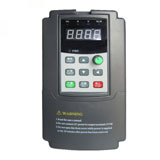
 High quality frequency inverters for electric motor speed controls in energy-saving solutions.