What is a frequency inverter?
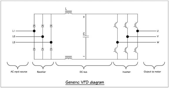
A frequency inverter changes output voltage frequency and magnitude to vary the speed, power, and torque of a connected induction motor to meet load conditions. A typical frequency inverter consists of three primary sections:
Rectifier Intermediate circuit/dc bus Inverter
You may notice that The Figure looks suspiciously similar to that for a double conversion UPS. In fact, the primary difference between the two is that the controls for inverter section in a UPS attempt to maintain consistent voltage and frequency output regardless of current output as opposed to varying voltage and frequency with generally consistent current output to speed up or slow down a motor load. Consequently, frequency inverters are typically rated in terms of maximum current output, while UPSs are rated in terms of power output.
Although the exact configuration of each section of the frequency inverter may vary from manufacturer to manufacturer, the basic structure remains the same. The rectifier section consists of an array of fast-acting switches that convert an incoming ac voltage supply to a pulsating dc voltage. The intermediate circuit consists of a dc bus and associated circuitry to stabilize and smooth the pulsating rectifier output. The dc bus voltage is roughly 1.414 times greater than the incoming ac supply voltage, depending on design type. This dc bus voltage is made available to the inverter section, which synthesizes an ac sine wave voltage output from the dc bus voltage.
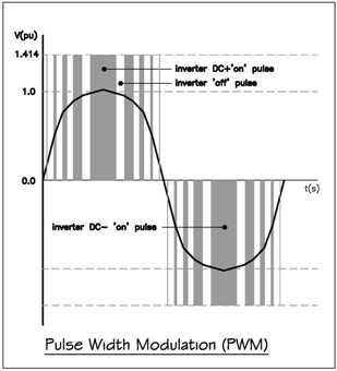
 The inverter section output is not a true sine wave but an approximation based on the principles of pulse width modulation (PWM), which is the predominant inverter technology. An array of fast-acting switches in inverter section produces voltage pulses at a constant magnitude proportional to the dc bus voltage. In a 3-phase frequency inverter, there are six switches with a pair of switches for each phase. In each pair of switches, one switch generates the positive component of the sine wave and the second generates the negative component of the sine wave from the dc bus voltage. The longer that the switch is "on," the higher the output voltage; conversely, the longer that the switch is "off," the lower the output voltage. This duration of on-time for each pulse is called pulse width. The time duration/intervals of these positive and negative dc voltage pulses determine the synthesized ac output voltage and frequency.
The speed at which these switches can turn on and off is called the carrier frequency. When the carrier frequency is increased, the associated output can have much higher resolution, resulting in a smoother output waveform with less ripple/distortion. This smoother output can improve motor torque performance at low speed and decrease audible motor lamination noise. In addition, faster switching has the potential for better inverter output controllability with associated improved dynamic response.
 Older inverter designs typically used silicon controlled rectifiers (SCR) or bipolar junction transistors (BJT) as the switching components. SCRs can operate in the 250 to 500 Hz range, while BJTs can operate in the 1 to 2 kHZ range. Most modern frequency inverters use insulated gate bipolar transistors (IGBT) for the inverter section. IGBTs can turn on and off at a much higher frequency, up to 20 kHz. The higher carrier frequencies associated with IGBTs offer some key advantages over older SCR and BJT inverters, but also have a severe trade-off to be discussed later.
IGBTs typically are not used in frequency inverter rectifier front-ends. frequency inverter rectifiers typically use SCRs or similar slower switching components. SCRs offer an advantage in that their simpler design is more robust given variable input voltage quality and have a relatively low cost. However, just as it was alluded that the higher carrier frequency of the IGBT on the inverter can cause issues, so can a lower frequency of SCRs on the rectifier front end. These slower switching frequencies on the front end can cause excessive harmonic distortion in the voltage source. Depending on the magnitude of the total harmonic distortion introduced by the frequency inverter and what other loads (lighting, computers, etc.) are sharing the same service, mitigation may be required in accordance IEEE 519-1992. Some mitigation may be achieved by using a 12-pulse inverter instead of a 6-pulse, or adding line reactors or a phase shift zig-zag type transformer used for drive isolation. Drive isolation transformers were designed to protect the frequency inverter from interference from upstream power disturbances. They do very little to mitigate the magnitude of harmonic currents that frequency inverter reflect back into the power system.
Rectifier Intermediate circuit/dc bus Inverter

You may notice that The Figure looks suspiciously similar to that for a double conversion UPS. In fact, the primary difference between the two is that the controls for inverter section in a UPS attempt to maintain consistent voltage and frequency output regardless of current output as opposed to varying voltage and frequency with generally consistent current output to speed up or slow down a motor load. Consequently, frequency inverters are typically rated in terms of maximum current output, while UPSs are rated in terms of power output.
Although the exact configuration of each section of the frequency inverter may vary from manufacturer to manufacturer, the basic structure remains the same. The rectifier section consists of an array of fast-acting switches that convert an incoming ac voltage supply to a pulsating dc voltage. The intermediate circuit consists of a dc bus and associated circuitry to stabilize and smooth the pulsating rectifier output. The dc bus voltage is roughly 1.414 times greater than the incoming ac supply voltage, depending on design type. This dc bus voltage is made available to the inverter section, which synthesizes an ac sine wave voltage output from the dc bus voltage.
 The inverter section output is not a true sine wave but an approximation based on the principles of pulse width modulation (PWM), which is the predominant inverter technology. An array of fast-acting switches in inverter section produces voltage pulses at a constant magnitude proportional to the dc bus voltage. In a 3-phase frequency inverter, there are six switches with a pair of switches for each phase. In each pair of switches, one switch generates the positive component of the sine wave and the second generates the negative component of the sine wave from the dc bus voltage. The longer that the switch is "on," the higher the output voltage; conversely, the longer that the switch is "off," the lower the output voltage. This duration of on-time for each pulse is called pulse width. The time duration/intervals of these positive and negative dc voltage pulses determine the synthesized ac output voltage and frequency.
 The speed at which these switches can turn on and off is called the carrier frequency. When the carrier frequency is increased, the associated output can have much higher resolution, resulting in a smoother output waveform with less ripple/distortion. This smoother output can improve motor torque performance at low speed and decrease audible motor lamination noise. In addition, faster switching has the potential for better inverter output controllability with associated improved dynamic response.
 Older inverter designs typically used silicon controlled rectifiers (SCR) or bipolar junction transistors (BJT) as the switching components. SCRs can operate in the 250 to 500 Hz range, while BJTs can operate in the 1 to 2 kHZ range. Most modern frequency inverters use insulated gate bipolar transistors (IGBT) for the inverter section. IGBTs can turn on and off at a much higher frequency, up to 20 kHz. The higher carrier frequencies associated with IGBTs offer some key advantages over older SCR and BJT inverters, but also have a severe trade-off to be discussed later.
IGBTs typically are not used in frequency inverter rectifier front-ends. frequency inverter rectifiers typically use SCRs or similar slower switching components. SCRs offer an advantage in that their simpler design is more robust given variable input voltage quality and have a relatively low cost. However, just as it was alluded that the higher carrier frequency of the IGBT on the inverter can cause issues, so can a lower frequency of SCRs on the rectifier front end. These slower switching frequencies on the front end can cause excessive harmonic distortion in the voltage source. Depending on the magnitude of the total harmonic distortion introduced by the frequency inverter and what other loads (lighting, computers, etc.) are sharing the same service, mitigation may be required in accordance IEEE 519-1992. Some mitigation may be achieved by using a 12-pulse inverter instead of a 6-pulse, or adding line reactors or a phase shift zig-zag type transformer used for drive isolation. Drive isolation transformers were designed to protect the frequency inverter from interference from upstream power disturbances. They do very little to mitigate the magnitude of harmonic currents that frequency inverter reflect back into the power system.

 High quality frequency inverters for electric motor speed controls in energy-saving solutions.

